TechBot1...........
A line following robot. by James Vroman
![]()
Design Goal:
The TechBot1 is a small line following robot designed for for the
1998 Embedded Systems conference in San Jose California. It was
built by Jerry Merrill and myself and was designed as a promotional
robot that would follow a black line drawn on a dry erase board.
![]()
Motive Power:
The TechBot1 uses 2 Cirrus CS-70 servos that have been modified
for full rotation and have had their controller boards removed to
convert them from servos to gear motors.
Servos are a common motive power for small robots due to their
low cost, ready availability, standardized sizes and the fact that it
only requires 1 bit on your processor to control the motor.
We initially tried this approach but found that the speed control was
very minimal with a finer control needed for this application. The
servo controller boards were then removed and the wires soldered
to the motor terminals and case ground. The motors were then
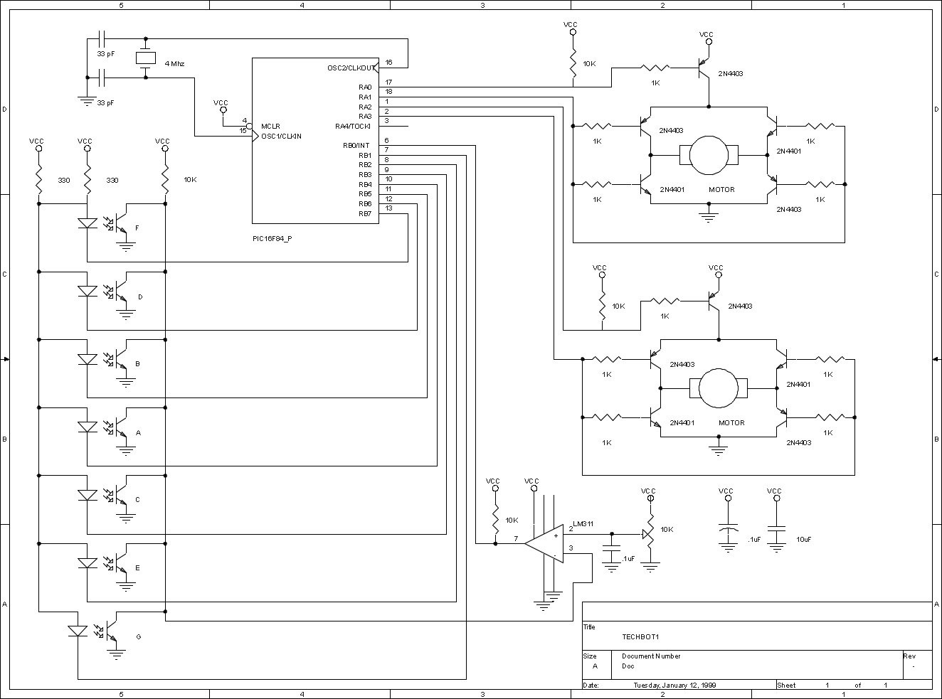
controlled by an H-bridge circuit to allow direction and speed control
with only 2 processor bits per motor. Initially a 4 transistor Bridge was
used but during power up the transistors would turn partially on and
start conducting. This was corrected by adding a 5th transistor to the
top of the H-bridge to control motor power. This also simplified the
software into having one bit for direction and another bit for
power/speed control per motor.
![]()
Sensors:
In order to follow the line I/R reflective sensors were used to
detect if a line was present or not. The sensors chosen are the
QRB1114 from QT Optoelectronics and have a focal point of
about 1/4 inch. They are available from DIGI-KEY.
Most line followers use 2 or 3 sensors of this type to do their
detection. This works but does not give the ability to follow
lines with very tight turns. We used an array of seven sensors
arranged in an "inverted V " arrangement placed
under the front of the robot behind the skid wheel. The sensors
are wired with all the receivers connected in parallel and fed to
an LM311 comparator to set the threshold trigger level with it's
output fed to a processor bit. Each transmitter LED is connected
through a current limiting resistor to a processor bit. This allows
the entire array to use 8 bits for the sensors.
![]()
Processor:
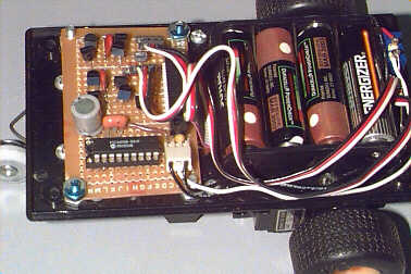
The PIC16F84 was chosen for it's small size, easy reprogramability
and interrupts ( the fact that we manufacture a PIC processor
emulator also helped in this decision). It is clocked at 4 MHZ by
a ceramic resonator and is powered by 4 AA rechargeable batteries.
These same batteries power the motors. This is usually not recommended
since surges in motor current can affect the processors operation, but with
decoupling caps in place and the watchdog timer being used in the
software no problems were experienced. The watchdog could reset the
processor if it went stupid before you could ever see it act up.
![]()
Mechanical:
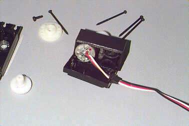
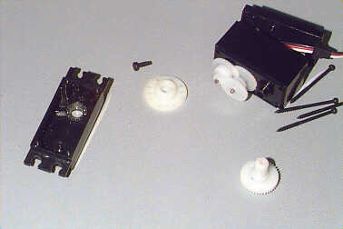
The servos were modified for full rotation by disassembling the servo
to gain access to the gear compartment. The main gear is then removed
and the stop that keeps it from rotating removed with an hobby knife.
The plastic key that keeps the feedback pot hooked to the main gear is
removed to allow full rotation without moving the feedback pot. Once
it was determined that the servo controller board did not provide
enough control, it was removed and the feed back pot removed as well.
The wires were removed from the control board and resoldered to the
motor terminals. The servos were reassembled and taped together.
This assembly was then attached to the bottom of a plastic case with
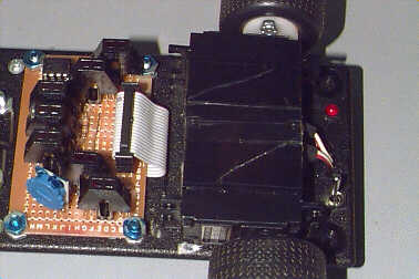
double sided tape. For this application the circuitry was split into a
sensor board and a processor/h-bridge board. The two boards were
connected by a ribbon cable. The entire assembly could be built on
one circuit board with the same board being used as the chassis.
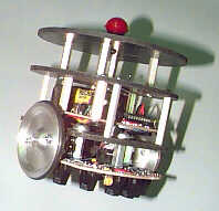
The sensor board is mounted under the front of the chassis with
the processor/motor control board above. A skid wheel (closet
roller wheel with a music wire frame) is attached to the front
of the robot.
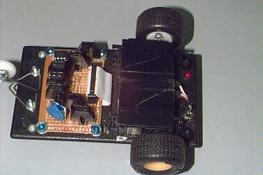
The battery holder is mounted over the motors to keep the weight
to the back and over the drive wheels.
The drive wheels were salvaged from a toy car and bolted to the
servo horns with #2 bolts. Hot glue will work for a while but
eventually will come loose. Both the Dallas Personal Robotics Group
and the Seattle Robotics Society have more information on
modifying servos for use in robotic applications.
![]()
Firmware:
The program is divided into 3 sections - The main program loop,
The pwm isr ( pulse width modulation interrupt sub routine) and
The action routines. The program functions to turn on the
transmitter portion of the sensors in order of priority and see
if a line is seen by the receiver section. The outer sensors are
tested first. If a line is seen then one motor is reversed while
the other continues forward. If no line is seen the next set in
are checked. If a line is seen here then one motor is stopped
while the other continues forward. If no line is seen here then
the next set in is checked. If a line is seen here then the speed
of one motor is reduced while the others speed is maintained.
If no line is seen by these sensors then the centermost sensor
is checked. If a line is seen here then the motors are set for
both full forward (we reduced this from full speed for better
reliability). If no line is seen by this last sensor than the last
motor setting is maintained in hopes of finding the line again.
Once a sensor detects a line and sets the motor settings then
the sensor routine is started again. In this manor priority is
given to the outermost sensors for the biggest corrections
with the more minor corrections being serviced last. More
details on this can be seen in the code listing. The firmware
was developed using the ClearView Mathias PIC emulator
and assembler which can be downloaded for evaluation
from HTTP://www.tech-tools.com
![]()
Real world:
The robots worked well with a run time of over 6 hours
per battery set. Three robots were built for the show and
all were still running at the end of it. The reliability and
the crowd that they attracted was better than we had
hoped for.
![]()
What's next?
The firmware could be updated to give more decision
capability and a memory of the corrections. If the robot
gets off course and intersects a line with both outside
sensors it can sit there and oscillate till a sensor clears
the line ( this caused many laughs at the show). A search
capability that if the line is not seen in a certain period
of time it can run a search pattern to locate the line
would be a good addition. With only one I/O line left
unused the hardware expansion is limited but I/O lines
can be recovered by using a 74HCT138 to use three lines
instead of seven for driving the sensor LEDs. I have
implemented this in my JavaBot1 with no degredation
in operation.

Add a speaker or sound effects chip. Robots
that make noise get far more attention than ones that do
not. The recovered I/O lines could be used for more sensors
or as a buss to talk to other processors.
Only your imagination will limit you.
![]()
Jerry Merrill is the founder and CEO of TechTools, a company
that specializes in memory and "PICmicro" emulation products
and development systems.Jerry has been involved in electronics
for over 23 years.
![]()
James Vroman is a Technical sales and support representative
for TechTools and an active member of the Dallas Personal
Robotics Group. James has been involved in Electronics for
over 15 years and can be reached at james@vroman.com.
![]()
Sources:
DigiKey-HTTP://www.digikey.com
TechTools - HTTP://www.tech-tools.com
Dallas Personal Robotics Group - HTTP://www.dprg.org
Seattle Robotics Society - HTTP://www.seattlerobotics.org
James Vroman -HTTP://www.james.vroman.com